RB Robotics
|
|
|
RB Robotics |
|
|
||
|
|
Approximate Build Time: Parts List
Assembly Steps:Here are the assembly instructions for the Shutdown Board. I take no responsibility for any damage from these instructions. Please report any inaccuracy in the assembly instructions. Colors and styles may vary.
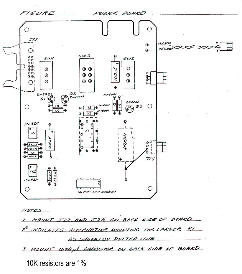
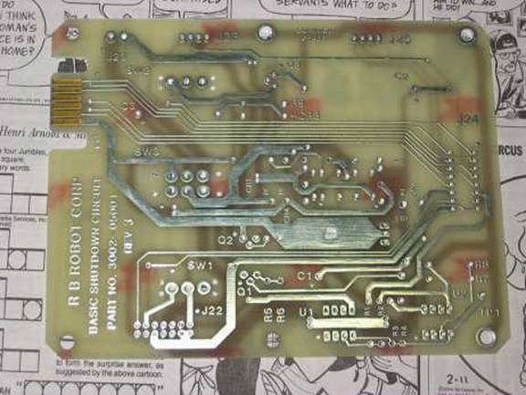
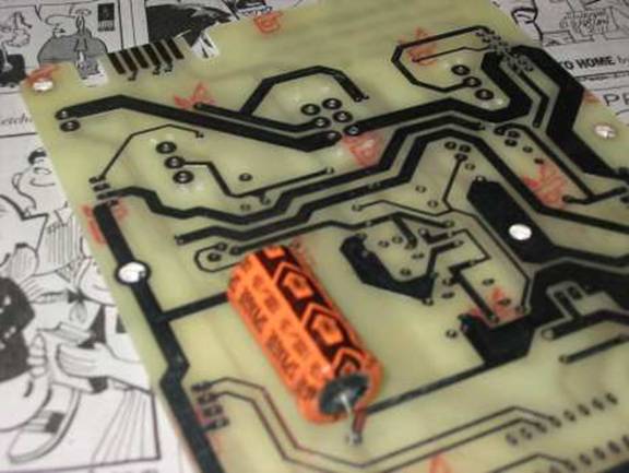
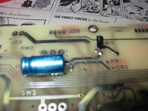
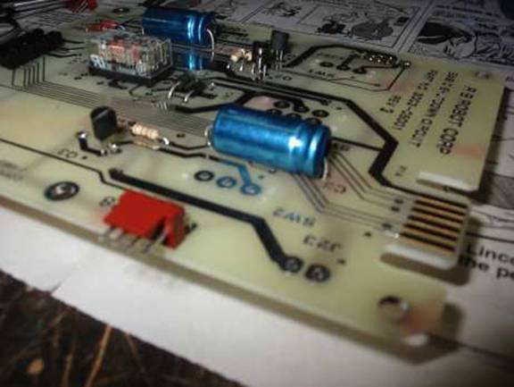
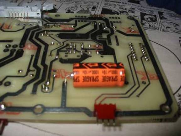
1. Place the 1000 µF capacitor (C2) on the BACK of the board (bottom left on back, as pictured). The negative end points toward the top of the board (the board’s built-in plated edge connector)
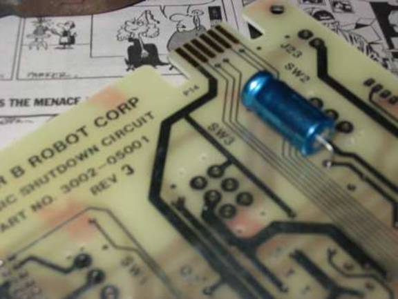
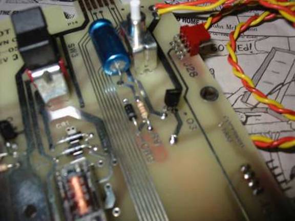
2. On the front of the board, mount one of the 100 µF capacitors (C3) just below the edge connector. The positive end goes toward the edge connector.
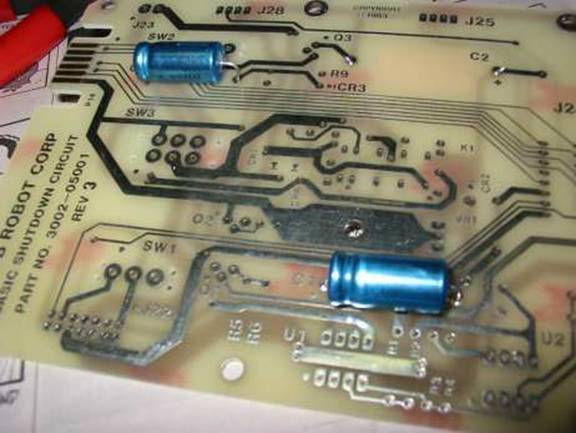
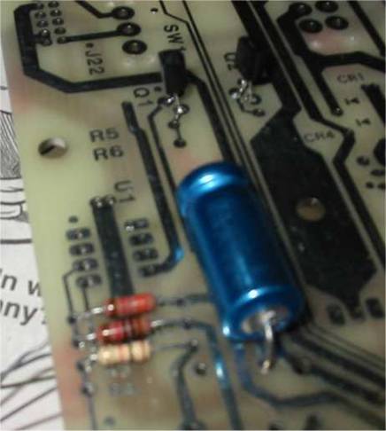
3.) Place the remaining 100 µF Capacitor (C1) in the spot indicated. The positive end faces towards the end of the board with the edge connector (the same direction as C3) .
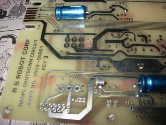
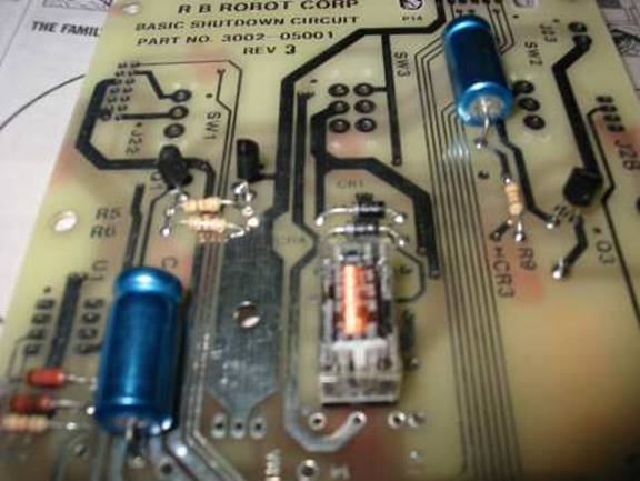
4.) Place transistor Q1 (2N2907) in place as shown. The flat side faces toward the closest edge (the left when the board is facing the front and the edge connector is on the top.)
5.) Q21 (2N2222) in place as shown, next to Q1. The orientation is the same as for Q1.
6.) Install transistor Q3 (2N2222) with the flat side facing toward capacitor C3.
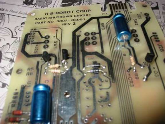
7.) Install R1, R2, R3 and R4 in the spots for them next to capacitor C1. R1 (closest to where U1 will go) is 33.2K, R2 is 10K, R3 is 1K, and R4 is another 10K.
8.) Install R7 and R8 as shown. R7 is a 33.2K resistor, and R8 is a full 100K.
9.) Install R5 and R6 near transistors Q1 and Q2. Both are 1K.
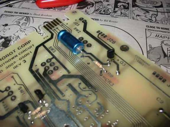
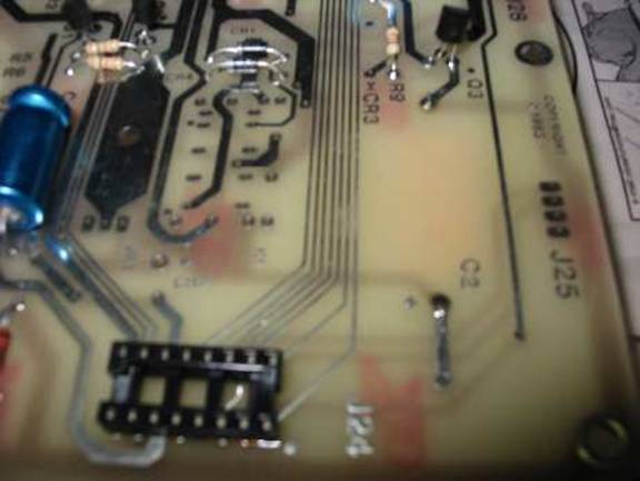
10.) Resistor R9 goes near transistor Q3. This is yet another 1K resistor.
11.) Install CR1 and CR4 (both IN4001) as shown. The marked ends must face towards R5 and R6.
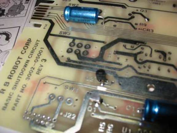
12.) Install CR3( also a IN4001) as shown (ignore the other components in the picture for now). The marked ends must face towards the bottom of the board (away from capacitor C3).
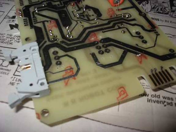
13.) Install a 16 Pin Dip Socket for J24, near the bottom of the board. Pin 1 of the socket is closest to C2 (the capacitor on the back of the board.)
14.) Install the Relay in the area shown. The board is designed to allow for different types and sizes of relays, but a relay will only fit in a certain way. Make sure all the pins go into holes without forcing. For the smaller type, there should be spare holes above, below, and to the right of the relay, but none on it’s immediate left.
15.) On the back of the board, mount and solder a 14 pin header (the grey one) for J22.
16.) Mount a 4 pin header on the top of the board for J28 (near C3.)
17.) Mount another 4 pin header for J25 on the back of the board, near C2 (the capacitor on the back of the board.)
19.) Install the Sonar Power cable at J23, near capacitor C3. The orange wire is closest to the edge connector, and the yellow wire is closest to J28.
20.) Install SW3 as shown. This is the rocker switch. Make sure the mounting tabs for this switch and the other two switches go though the provided holes.
21) Mount SW1 and SW2 in the proper slots. One is to the left of SW3, and the other is to the right. Both of these are momentary pushbuttons.
22.) Mount 2 8 pin dip sockets near capacitor C1. Pin 1 for both face the top of the board (there is a dot near the socket holes that shows where pin 1 goes.)
23.)Install a wire as shown. This wire runs from one of the paths for C2 to the second from the bottom pin for J25.
24.) Install CR2 as shown. This is the IN5402 diode. The marked end faces away from capacitor C1.
25.) Taking the usual antistatic prevention measures, mount ICs U1 and U2. Both are 8211 chips. Both mount with pin 1 facing the upper-left corner. Place a square button cap on SW1, and a round one on SW2. Remember to keep the square button oriented correctly when installing this board into the interface panel. Alternatively, wait until after you put the interface panel together, and then install the button caps.
|
|
|||||||||||||||||||||||||||||||||||||||||||||||||||||||||||||||||||||||||||||||||||||||||||||||||||||
|
Copyright © 2005 RB Robotics | |