RB Robotics
|
|
|
RB Robotics |
|
|
||
|
|
Updated! 4-8-2007
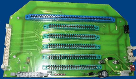
Back Plane Board Approximate Build Time: 1 hour Parts List
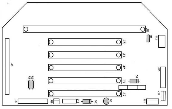
( ) Locate the Back Plane PCB (marked mother board) and the Back Plane Pack Refer to the diagram 1 below ( ) Install R1 - 1K Ohm Resistor (Red-Black-Brown-Gold) ( ) Install R2 - 150K Ohm Resistor (Brown-Green-Yellow-Gold) Note: Position R3 is NOT used ( ) Install C1 - 1000F Capacitor - Make sure that the + matches the + on the board ( ) Install D1 - 1N5402 Diode - Make sure the band goes to the connector marked J10 ( ) Install D2 - 1N5402 Diode - Make sure the band goes toward C1
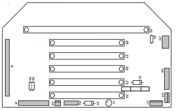
Diagram 1 ( ) Install 2 fuse clips. You may need to bend the tabs out straight and then solder them to the board. ( ) Install 1 Amp Fuse ( ) Install 14 pin Socket at J14 ( ) Install 2 pin header at J19. Make sure that the lock tab is on the inside of the board ( ) Install 4 pin header at J11. Make sure that the lock tab is on the inside of the board ( ) Install 5 pin header at J13. Make sure that the lock tab is on the inside of the board ( ) Install 8 pin polarized header at J14. Make sure that the missing pin is on the side closest to J19 ( ) Install 10 pin header at J10. Make sure that the key is on the inside of the board. ( ) Install 20 pin locking header at J9. Make sure that the lock tab is on the outside. ( ) Install 50 pin locking header at J6.
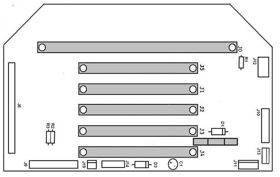
Make sure that the key is on the outside. In the following steps you will be installing several long connectors. Make sure that the entire connector is flush to the board BEFORE soldering all the connections. Align the connector and try holding it down with a piece of tape. ( ) Install J4 - 2x22 pin connector - Green in color ( ) Install J3 - 2x22 pin connector - Green in color ( ) Install J2 - 2x22 pin connector - Green in color ( ) Install J1 - 2x22 pin connector - Green in color ( ) Install J5 - 2x22 pin connector - Green in color ( ) Install J0 - 2x50 pin connector - Blue in color This concludes the assembly of the Back Plane Board. Set this aside until called for later.
|
|
|||||||||||||||||||||||||||||||||||||||||||||||||||||||||||||||||||||||||||||||||||||
|
Copyright © 2005 RB Robotics | |